Foucalt Tester
This page describes my current Foucalt tester. The tester is based on the tester described by Texereau in his book How To Make A Telescope.[1]
Photos
Below is photos of the tester:
 |
 |
 |
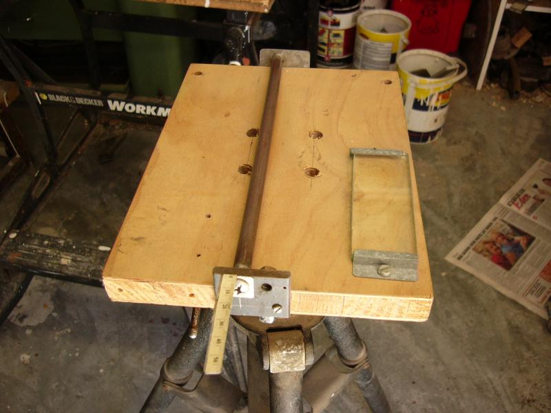 |
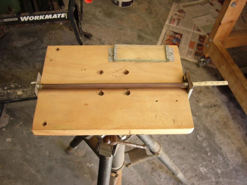
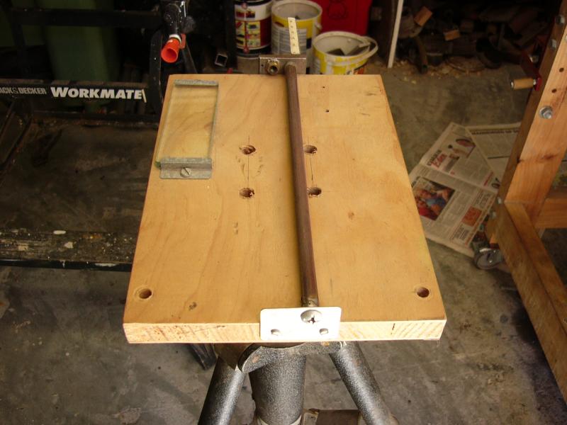
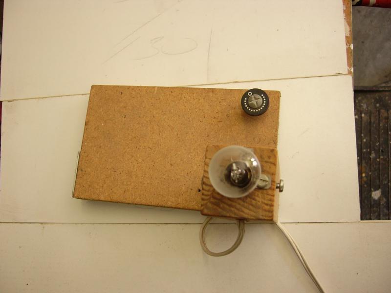
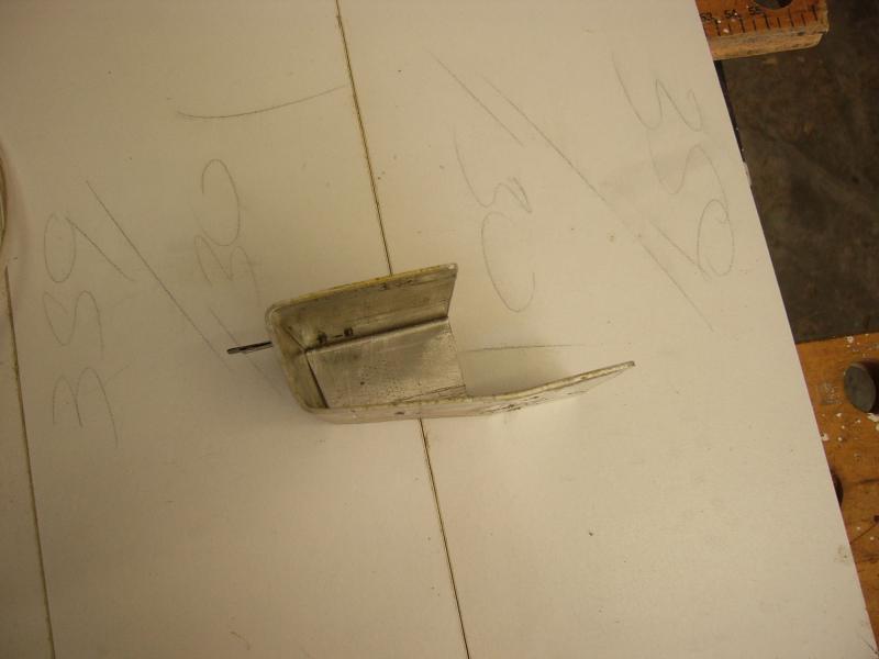
| The base of the Foucalt tester. The tester moves on a piece of pipe which should be relatively straight. | Base seen from side. | ||
 |
 |
 |
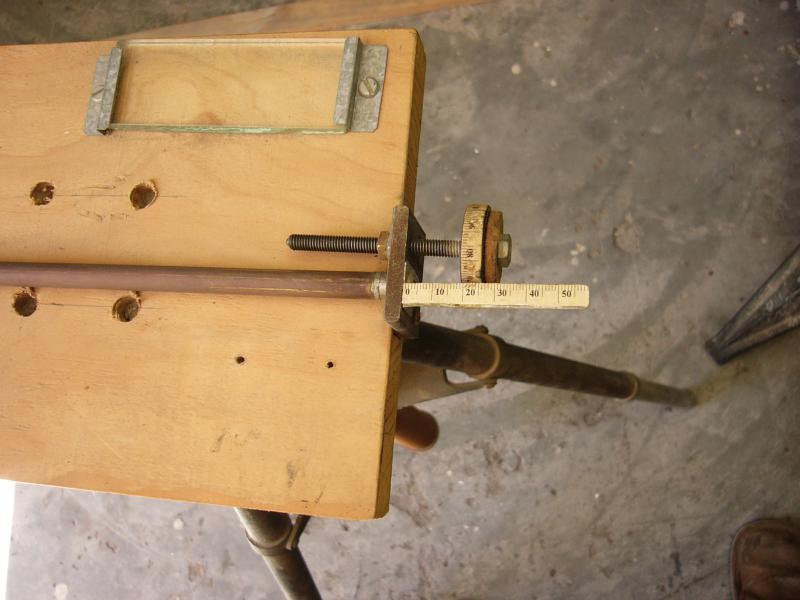 |
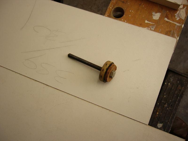
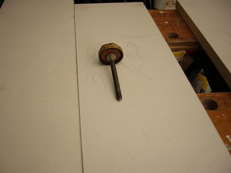
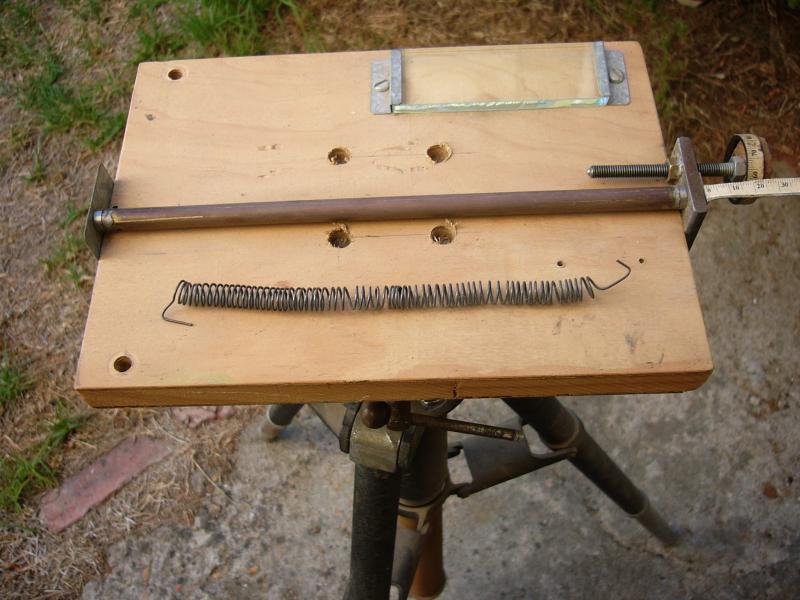
| The set screw with which the tester is moved. The scale with 100 divisions was made by drawing it on CAD and then printing it. | The point of the set screw can be made sharp with a small flat at the front. But if it is not exactly square with the axis it will introduce a periodic error in the movement of the tester. A better way is to fix a small roller ball in the point of the screw. | The base with set screw fitted. The combination of the scale on the base with 1 mm divisions and the 100 divisions on the set screw make it possible to take readings of 1/100th of a mm. | |
 |
 |
 |
 |
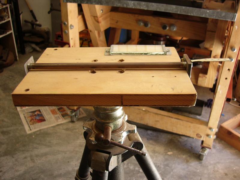
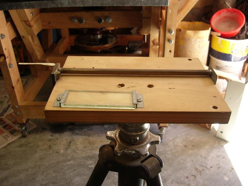
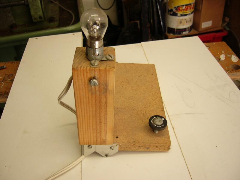
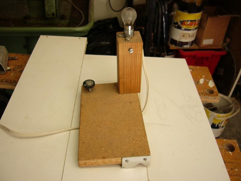
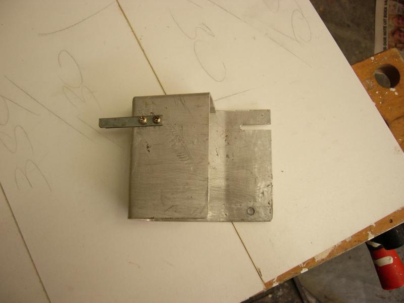
| The slide of the tester. Light is provided by a 12 volt motorcar headlight lamp. | This side of the lamp should be frosted with fine sandpaper in order to provide uniform lighting of the mirror. | The slide seen from the side. The set screw rests on the piece of glass on the base and is used to set the width of slit during testing. | |
 |
 |
 |
 |
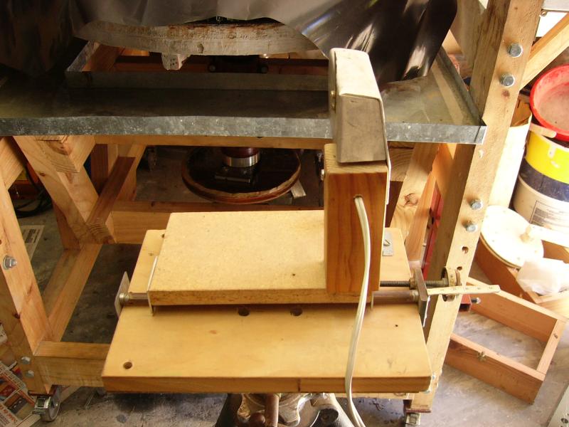
| The lamp screen. A small hole directly opposite the lamp allows light to travel to the mirror. Half of the hole is covered by a razor blade. Another plate is placed over the razor blade to prevent it from cutting one. | The lamp screen seen from the side. | The lamp screen fitted to the slide of the tester. | The whole of the tester. The lamp screen is fixed to the slide with a screw. |
 |
 |
 |
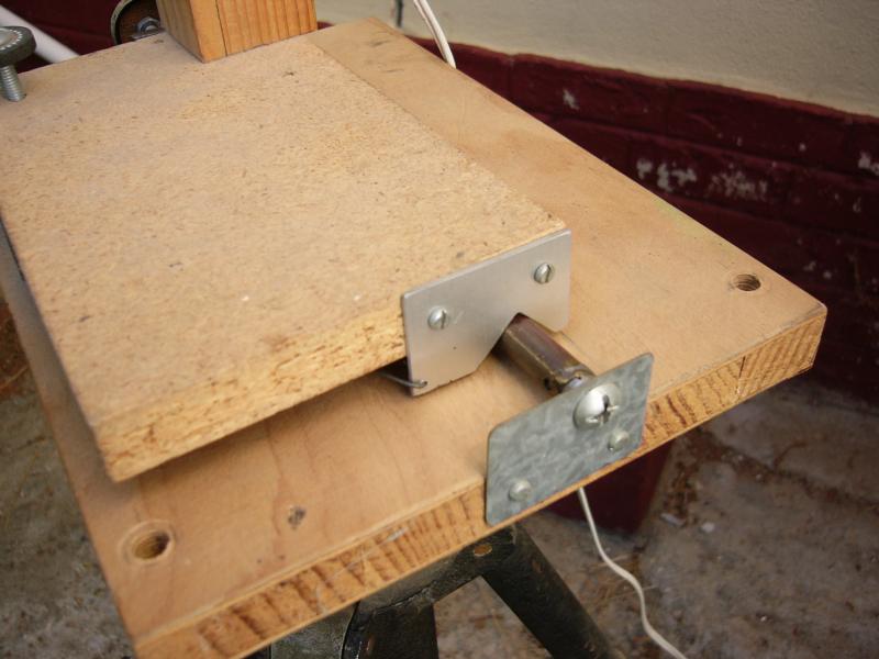 |
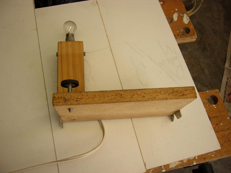
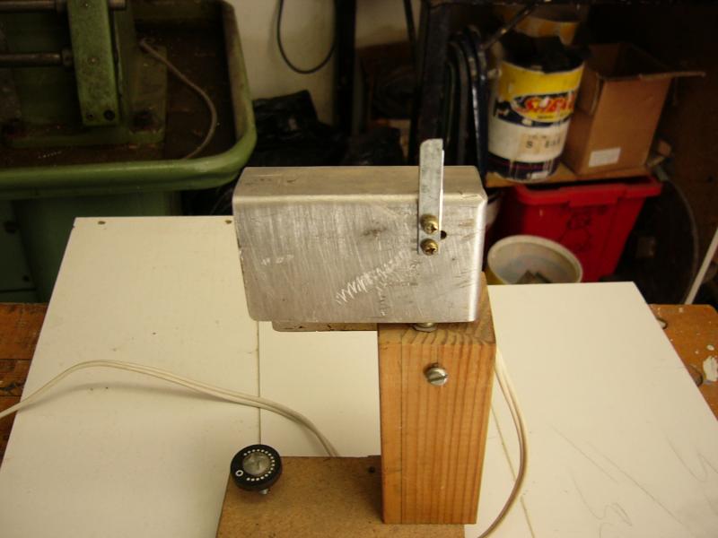
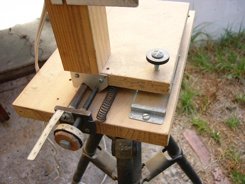
| The tester seen from the side. | The slide is kept against the setscrew by a spring made from a thick quitar string. | The spring hooks into a hole at the right of the setscrew. | On the other side the spring hooks into a hole in the V-plate. |
 |
|||
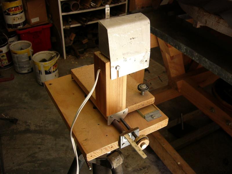
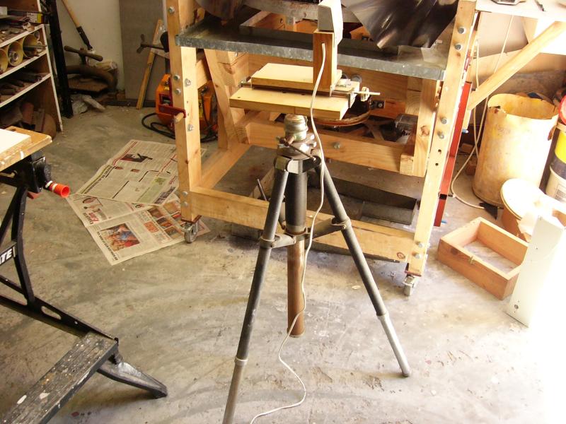
| The tester is mounted on an old camera tripod. |
Disadvantages of the tester
The disadvantages of the tester is as follows:
- The 12 volt lamp of the tester gives off a lot of heat and one runs the risk of being burned by it. It limits how near one can bring your eye to the slit of the tester. Especially if one is wearing spectacles since the spectacles adds to the problem.
- The size of the lamp limits the minimum distance between the light source and the returning rays from the mirror. Ideally one wants them as close to each other as possible to limit the error caused by it.
Improvements
The following improvements can be made to the tester:
- Replacement of the lamp with a super bright green LED.
- Making the brightness of the LED changeable.
- Adding an on/off switch for the LED.
- Add another uncovered LED with an on/off switch to aid alignment of the tester.
- The scale of the set screw can be replaced with a dial indicator.
References
1. Texereau, Jean. How To Make A Telescope. Interscience Publishers, Inc. 1957.